The Falkirk Wheel Is One Crossing on Two Canals
A boat lift looks like a destination from the bank. From a canal boat it is one step in a journey with approaches, different water levels and another set of locks.
In this story 4 sections
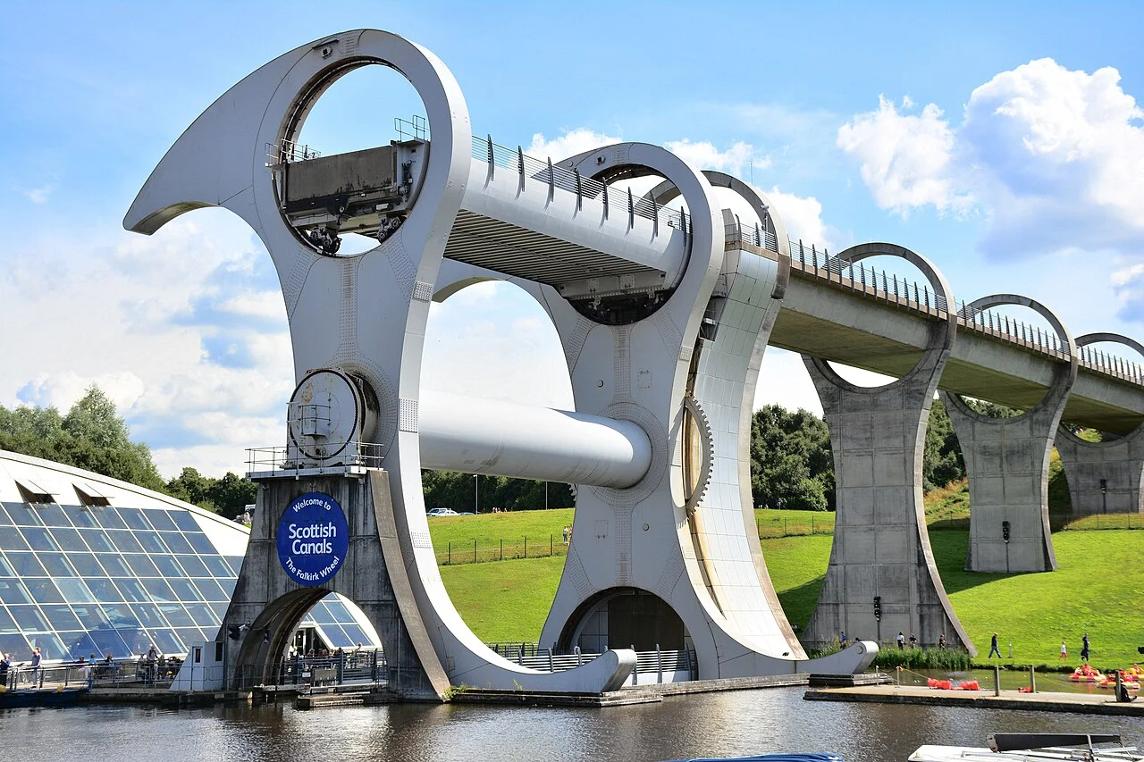
The Falkirk Wheel looks complete from the water below. Two arms swing around a central axis. When the structure turns, a boat can travel with a trough of water and arrive at another level, upright and still afloat. A map of a longer journey gives the scene a different weight. The boat still has to get out of the trough. Its next stretch follows a raised waterway and then continues through other parts of the connection. The useful line on the map is the chain of places a boat can enter and leave, with the circle of the wheel occupying a small but memorable stretch.
The wheel connects the Forth and Clyde Canal with the route up to the Union Canal. The two waterways cross Scotland through different ground and do not share one continuous water level. Historically a flight of locks handled the local change of level. The modern connection reopened navigation between the canals with a rotating lift and other works. The National Transport Trust describes a change of about 24 metres at the wheel, while Scottish Canals gives about 35 metres between the connected canals. Further changes of level occur beyond the lift. Those figures describe different spans of the route.
Trace the approach before watching the machine
From a position by the lower basin, follow the water to the opening of the bottom trough. The visible wheel has its own outline. A boat needs a straight and clear enough path from the rest of the water to an entry when the trough is in position. It also needs some arrangements for waiting and moving on when the equipment is ready. The extra water around the point of entry is part of the journey. So are the signals and gates that determine when a shared piece of equipment is available.
Once the boat is inside a trough, the moving object is a controlled body of water as well as a vessel. Before a trough can rotate, it has to be closed off from the waterway. At the other end, it needs to meet a new level and open onto a suitable route. Follow one approach in a photograph and mark where you think a boat would first stop being able to continue on its own. A visitor on foot can cross several boundaries without considering them as separate events. Someone navigating a loaded boat needs each one to be ready in sequence.
That accounts for a common difference between an impressive short video and a useful description of the route. A film usually begins just as rotation starts and ends as the boat reaches another level. For a person travelling, time at the meeting points matters. The size of the boat and its ability to use the connecting sections can matter as much as whether the trough itself can carry it. Scottish Canals publishes navigation guidance for those sections, including dimensions. Treat that operational guidance as the place to check a real trip: access, booking and restrictions can change.
Why a boat does not add its full weight to a filled trough
An ordinary object placed in a dry moving tray adds its weight to the load. A boat placed in a filled trough behaves differently if everything is operating at the intended level. It floats by displacing an amount of water equal in weight to the boat. Consider two troughs filled to the same intended level. If one receives a floating boat and enough water is displaced to restore the level, part of the mass previously present as water is now present as a boat. There can be a close balance between the loaded and unoccupied troughs. The cancellation follows from the weight of displaced water, not from the boat being light enough to ignore.
It helps to keep the conditions around that explanation attached to it. If the water in one trough is at a different level, that changes the balance. A vessel supported by something other than the water would be a different case. A real lift also has mass in its bearings, drive and container structure, and must overcome resistance and control its motion. Balance makes movement easier to manage. It does not provide power or make design of the rest of the machinery unnecessary. The most accessible part of the physics is the substitution of water for the weight of something floating in it.
Another separate problem is keeping people and boats upright while the arms turn. Picture a solid tray fixed to an axle: at the end of half a turn, it would be upside down. The troughs have to stay horizontal while the arms change orientation. An account of the wheel can distinguish the mechanism that brings the troughs round from the mechanism that keeps them level. Observing a boat and watching the underside of its trough during a safe public viewing are useful ways to separate those movements. The boat goes round the centre while its everyday relationship to the water under its hull stays nearly the same.
Look along the upper approach
From the side of the lift, a boat high in the air may seem to have nowhere to go. The raised channel at the top is what turns an ascent into a useful connection. The upper stretch leads toward the tunnel and further locks on the route to the Union Canal. Once one piece of water reaches the new level, features farther along still have to accommodate navigation through land at a different height. The route occupies a corridor rather than a single point on a map.
Ask what the passage would look like without a view of the turning wheel. An ordinary stretch of channel leads through a system of gates, tunnels and changes of level. A few of those things stay hidden from popular photographs, but they help determine how the waterways work as a pair. Constraints on a tunnel or lock can govern the trip even where a basin looks broad and open. Information about the whole route is therefore more valuable to somebody deciding whether they can travel it than dimensions taken only at a memorable landmark.
The traced path also improves a comparison with the former flight of locks. Several ordinary locks can distribute a height change across a longer series of steps. A wheel concentrates one considerable change in a smaller area and gives vessels a different sequence of waiting and movement. The physical landscape still demands some transitions before and after the lift. A map that shows only the machine loses those transitions, just as a map with only the broad canal corridors can make the local arrangement seem trivial. Use both scales to see how the renewal gave old water routes a new connection.
At an ordinary lock, imagine a boat entering a chamber that already matches the height of the approach. After the doors close, water is admitted or let out to match the level of the exit. The boat’s position changes along with the level around it. At the wheel, the body of water in one trough is carried to another level as a unit. A gate still has to match an adjacent waterway before it can open. Watching the apparent sameness at the door and the difference in how the level changes makes it easier to compare the two solutions. Each provides a sequence the boat can follow while remaining afloat.
Now consider the waterway from a towpath rather than a boat. Walking routes and boat routes can diverge at a gate, lock, tunnel or bridge, and their conditions are governed separately. A visitor can often get an excellent view of a piece of the route from a place a person on the water could never occupy. A voyage account and a pedestrian account can thus be complementary. Keep track of which one a photograph represents before using it to describe the approaches.
On a small itinerary, label both the upper exit from the wheel and the point where the route joins the Union Canal. Seeing two different labels on the route helps prevent one name from standing in for every bridge, lock and stretch of channel in between.
Read the change from both directions
Finally, try following the diagram of the route backwards. What a photograph labels the exit is the entrance to a passage in the opposite direction. A level is high when compared with the basin beneath it, and forms the starting point for weighing up the next lift or lock. Travel through a system tends to make landmarks appear in different orders from the ones that make sense on a visitor map. Approach, transfer, departure and waiting are good headings for your own account because each has a recognizable job in either direction.
The view from the lower basin remains an excellent place to see the machine. Keep a view of the upper channel beside it. The two pictures show what is sometimes missing when new machinery becomes a landmark: the places where the work starts and where it turns useful again. An upward trip by one trough is immediately intelligible and can be watched in a few minutes. The canal connection asks a longer question. It has to bring a boat to the point where it can enter that trough, then give it a route beyond the point where the rotation ends.